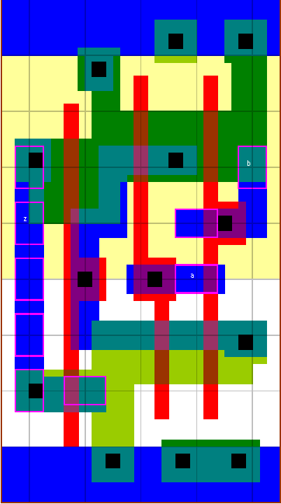
an2 standard cell family
2-I/P AND gate

The P/N ratio is set to 2 for both the NAND gate and the inverter. Two types of electrical gain between the NAND gate and the inverter are provided. The v0 version is a higher gain optimised for speed. The v4 version has each stage gain at 4, which optimises the speed for zero wireload and low power. The v4 version has higher Prop delays but lower input pin capacitances.
z:(a*b)
cell width
power
Generic 0.13um typical timing (ps & ps/fF), pin b.
leakage
dynamic
tR=PropR+RampR×Load(fF), tF=PropF+RampF×Load(fF)
lambda
0.13um
nW
nW/MHz
PinCap
PropR
RampR
PropF
RampF
an2v0x05
40
2.20
0.54
12.2
2.7f
70
4.95
91
3.82
an2v4x1
40
2.20
0.52
13.7
1.9f
87
3.33
119
2.66
an2v0x1
40
2.20
0.74
15.9
3.3f
71
3.31
89
2.58
an2v4x2
40
2.20
0.75
19.1
2.2f
94
2.13
121
1.68
an2v0x2
40
2.20
1.01
21.6
3.9f
74
2.12
91
1.65
an2v4x4
50
2.75
1.46
32.4
3.6f
94
1.07
115
0.84
an2v0x4
50
2.75
1.78
35.8
5.8f
76
1.06
94
0.83
an2v4x8
74
4.07
2.68
58.0
6.3f
91
0.57
113
0.45
an2v0x8
90
4.95
3.05
62.4
8.9f
78
0.57
99
0.44
 an2v0x05
 an2v4x1
 an2v0x1
 an2v4x2
 an2v0x2
 an2v4x4
 an2v0x4
 an2v4x8
 an2v0x8


