| vlsitechnology.org /IR drop /example 1 |
Example 1 |
IR Drop
- IR drop problem
- Power delivery
- chip illustration
- 1W core power
- 2W core power
- 15% power straps
- 1W 30% blocks
- 2W 30% RAM, 20% analog
- upper power straps
- reducing impact
- 1W power best
- 2W power best
- 1W best 30% blocks
- 2W best RAM, analog
- summary of method
- conclusions
- example 1
- example 2
Example 1 pages
The paper has presented a theoretical approach to sizing the power straps in an integrated circuit. Not surprisingly there are some differences between what is desired and what is achievable, and these are considered here with reference to a real example.
The technology is 6 layer metal and the core size estimate before adding any power straps is 3.5×3.5mm. The table of relative power strap widths and resistivities, and the fixed block area is given below.
| metal layer | 1 | 2 | 3 | 4 | 5 | 6 |
|---|---|---|---|---|---|---|
| kan | 100% | 100% | 100% | 100% | 200% | 200% |
| power strap allocation coefficient | ||||||
| kwn | 100% | 100% | 100% | 100% | 200% | 200% |
| power strap width coefficient | ||||||
| rn | 80 | 60 | 60 | 60 | 60 | 20 |
| metal resistivities in Ω per sq. | ||||||
| kcn | 75% | 100% | 100% | 100% | 100% | 300% |
| conductivity coefficient | ||||||
| mn | 50% | 50% | 50% | 50% | 50% | 0% |
| core area blocked | ||||||
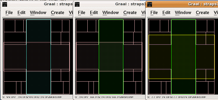
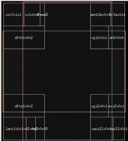
Power straps are equally divided vertically and horizontally, and the metal-5 and metal-6 straps will overlap the standard cells, as shown in the Graal screen shots on the right.
In Graal, the power strap allocation is drawn with the TALU1-TALU6 layers.

Graal screen shots of (from l to r) metal-2/3,
metal-3/4 and metal-4/5 power strap allocations.

Graal screen shot of metal-5/6 power strap allocation.