| vlsitechnology.org /IR drop /die size impact |
Impact of Power Straps on Die Size |
IR Drop
- IR drop problem
- Power delivery
- chip illustration
- 1W core power
- 2W core power
- 15% power straps
- 1W 30% blocks
- 2W 30% RAM, 20% analog
- upper power straps
- reducing impact
- 1W power best
- 2W power best
- 1W best 30% blocks
- 2W best RAM, analog
- summary of method
- conclusions
- example 1
- example 2
Derivations
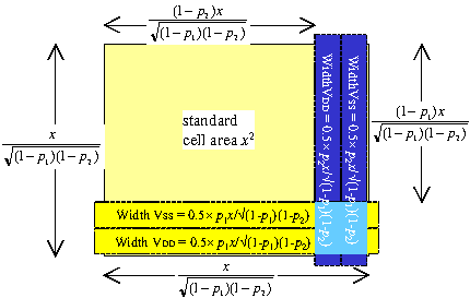
If we have a metal power supply using fraction p of the metal resources, and a core side of x, then the increase in the length of the core is not (x×p)%.
| It is | x |
| √((1-k(2)×p)×(1-k(3)×p)) |
referring to the figure on the right.
For example, for a power strap percentage of 15% both horizontally and vertically, this means that the increase in the core side is not 15% but 17.6%.
| Increase = | 1 |
| √((1-1×0.15)×(1-1×0.15)) | |
| = | 1 |
| 0.85 | |
| = | 0.176 |
We can see this from the drawing on the right.
Before power strap insertion, the die area is
| A = | x2 |
and after power strap insertion it is
| A = | x2 × (1-k(2)p) × (1-k(3)p) |
So that the ratio between the areas after and before power strap insertion is
| (1-k(2)p) × (1-k(3)p) |
and the ratio in the length of the side is
| √((1-k(2)p)(1-k(3)p)) |
In the special case where we make the horizontal and vertical power
straps equal, then k(2)=k(3)=1 and a core side
of length x will increase to
| x . |
| 1-p |

Both metal-1 and metal-3 horizontal power straps will block the placement of standard cells underneath. This means that one should aim to keep the fraction of metal-1 used for power straps the same as the fraction of metal-3. That is, p1 = p3, and they are used interchangeability in this paper.